Event Management System
Important Note
This project was created as a university project and is not suitable for production. There will be no active development on this project.
A system for the management of Security and Stewarding staff at events created as a final year project for my BEng Software Engineering degree. For this project and accompanying dissertation I was awarded 80%. Video demonstration is available here.
Project Aim
The aim of this project was to create a user-friendly system that would allow stewarding personnel at large events to easily report incidents directly to the control room of the venue. The control room would be able to view a dashboard containing the current state of the venue, as well as a live feed of requests and incident reports from the stewards and security personnel on the ground. The control room would then be able to more accurately determine appropriate action to take, and the time that a position is unattended by a steward will be cut to zero.
While the intended purpose for this system would be for venues, including companies that get contracted by venues to handle security, that host events such as concerts and sports games to deploy for their stewards and security personnel, it could also be easily adapted to function in other places where a large group of employees need to report to a central place, such as museums, hotels, and large stores.
Objectives
-
Create a simple to use mobile application for stewards to request assistance from security, cleaners, and supervisors with as little input as possible
-
Allow stewards to view the venue’s current alert status at a glance
-
Allow stewards to report incidents, such as falls, complaints etc., at the press of a button in an app
-
Allow control room operators to view the current state of each position in the venue
-
Allow control room operators to view a live feed of assistance requests and incidents from stewards
-
Reduce the time that a position is left unattended to zero
-
Enable control room operators to make more informed decisions as to further action
System Components
The system consists of three main components:
-
An Android app for Stewards to request assistance from the control room
-
A web dashboard for Control Room Operators to view assistance requests for events, and for Admins to manage Events, Venues, and Staff
-
A serverless AWS backend
Technology
For the infrastructure of the system, I decided to create a fully serverless backend that would be cost effective and that would scale to the unpredictable demand if this system was deployed in a production environment. For this I used the AWS CDK in order to write my infrastructure as code, and I used many AWS technologies such as Cognito, API Gateway, CloudFront, S3, Lambda, and DynamoDB.
For the mobile app I created an Android app that employed a single activity MVVM architecture pattern and was written using Kotlin, with Kotlin Compose for the UI and Dagger Hilt for dependency injection.
I created the web dashboard using ReactJS function components and hooks. I initially used Tailwind CSS for styling, however I switched it out for Styled Components later in development
System Architecture

0 - Web app is served from an S3 bucket that is behind a CloudFront distribution that allows HTTPS
1 - When a user logs in from either the web app or the Android app, a request is sent to AWS Cognito containing the user's username and password, if the username and password match a user stored in the User Pool, then an access token encoded in a JWT is returned.
2 - When an API request is made from a client it will contain an access token JWT in the Authorization header. When the request reaches API Gateway, the request will first be forwarded to an Authorizer Lambda before being passed to the actual feature Lambda.
3 - The Authorizer Lambda verifies the access token using the public keys provided by Cognito. The authorizer lambda will also verify the user has the appropriate role to access resources. There are several authorizers in use for the system that check if:
-
The user is an Admin
-
The user is a Control Room Operator or an Admin
-
The user is assigned to the position they are making the request for
-
The user is the same user that they are making a request for
-
The user is authorized to connect to the venue status WebSocket
-
The user is authorized to connect to the assistance request WebSocket
4 - Once a request has been authorized, the Lambda handler for that route is invoked which performs actions such as adding or retrieving data from Cognito and DynamoDB, or connecting to a WebSocket.
5 - The response from the Lambda is returned to the client which then handles it appropriately.
Data Design
For the main table of the system I opted to use a Single Table Design as DynamoDB is optimised for efficiency of retrieval as opposed to efficiency of storage.
Two main sections of data were to be stored in the main table: venues, and items related to events. Due to this I opted to use a Universally Unique Identifier (UUID) as the Partition Key. For venues, this was the ID of the venue, and for data related to an event such as the event details, assistance requests, and venue status updates this was the ID of the event. For the Sort Key, I used a field that I called “metadata”. This was where the type of the data was stored, for example whether it was a venue, an assistance request, a status update etc. If there was any additional identifying information required, I would append it to the end of the metadata, for example to store the UUID of an assistance request the metadata would be “assistanceRequest_UUID”. To assist retrieval of specific types of data I created a Global Secondary Index (GSI) on the metadata. This meant that I could retrieve all items with the metadata “venue” or “event” as if it were the Partition Key. I could also use this to retrieve all assistance requests by checking that the key started with “assistanceRequest” and likewise for venue status updates. With this table design I was able to retrieve all information related to an event at once by querying for the event’s ID, without any complex joins that would have to be performed when using a multi-table relational database.
As information related to WebSocket connections was completely unrelated to the other data being stored in the system I created a separate table for it.

An example of how data is stored in the DynamoDB table, note that some columns have been left out for simplicity’s sake.
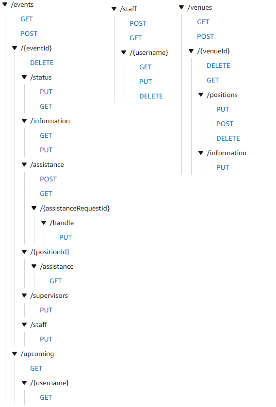
REST API

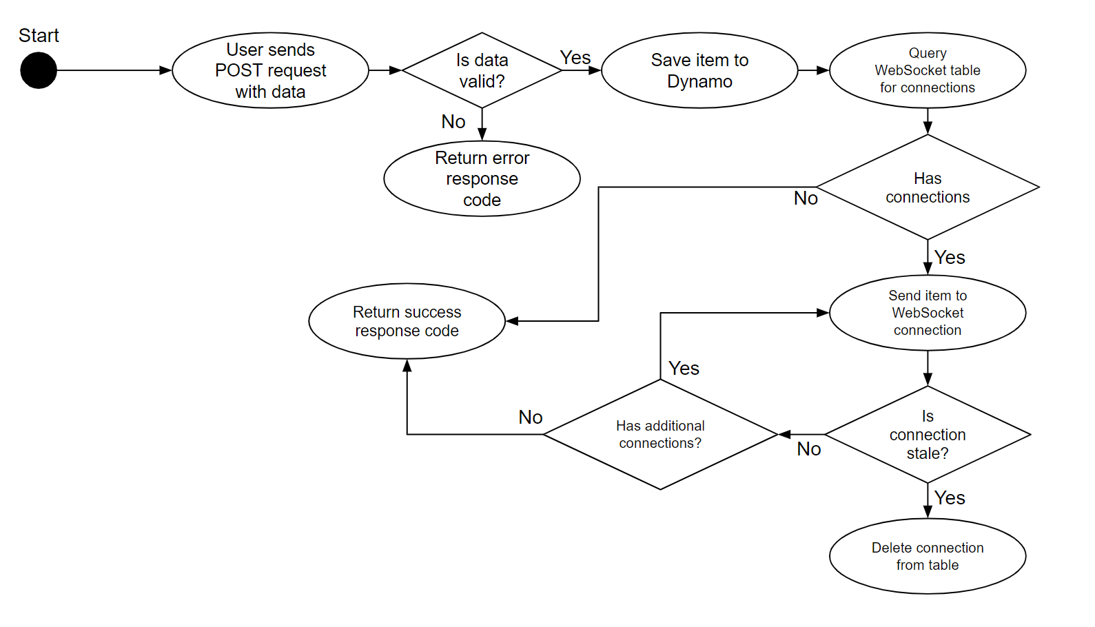
Generic WebSocket Lambda Flow

The above figure shows the flow that the code follows within a Lambda that adds an item to the database and then notifies connections to a WebSocket. A Lambda that implements this flow is the AddAssistanceRequest Lambda which saves an assistance request to the DynamoDB and then notifies all subscribers to the Assistance Request WebSocket of the new request.
The beginning of the flow is similar to a standard lambda where data is validated and then saved to the database. If the data is invalid - for example if it is missing a field or a field doesn’t meet the constraints - then an error response is returned. Once an item has been added to the database the WebSocket Connections table is queried for connections. The WebSocket Connections table contains the name of the websocket that the connection is for, the unique connection ID, and the event ID that the connection is subscribed to. With this schema the Lambda can query for a specific WebSocket. In the case of AddAssistanceRequest this is the assistanceRequest WebSocket. The list of connections to that WebSocket can then be filtered based on the event that the Assistance Request is for. The data is then sent to each connection via a POST request. Occasionally a connection may be stale, for example if a connection has been force closed without the proper disconnect procedure being followed. This is represented by a response code of 410 to the POST request. If a stale connection is encountered the details of that connection is removed from the Connections table. Once the data has been saved and all WebSocket connections have been notified, a success response code is returned from the Lambda.
Code Summary
The backend of the system refers to the CDK code for generating the AWS infrastructure, the code for each Lambda, as well as the code for the unit tests of the Lambdas. In total the backend consists of:
-
38 Lambdas
-
28 REST API routes
-
2 WebSockets
-
52 test files
-
271 unit tests
-
14 files defining CDK infrastructure
-
84 files defining Lambdas
-
Approximately 16000 lines of code
The React web dashboard consists of:
-
7 web pages
-
107 manually written files
-
Approximately 6700 lines of code
The Android app consists of:
-
3 screens
-
56 files
-
Approximately 2600 lines of code
In total the entire project comprises approximately 25500 lines of code between 313 files.